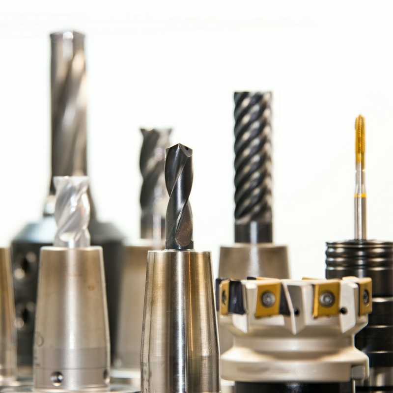
Mould cavities corrode, cutting edges chip, and steel tooling picks up material from the workpiece. A cavity running halogenated plastics develops pitting from acid gases released during moulding. A glass fibre reinforced part erodes the cavity and the gate. An end mill cutting hardened steel loses its flank to crater wear and then chips. These are surface failures, and they are the failures that PVD coating is built to carry. Mould and cutting tool coating adds a hard, chemically inert film a few micrometres thick, so that wear, corrosion and build-up are carried by the coating instead of by the tool steel.
Coating does not repair a damaged tool and does not replace sensible cutting parameters or good housekeeping. It is applied to tools that are sound and properly prepared.
Typical parts we coat
- Injection moulds, die casting moulds, stamping and drawing dies and powder metallurgy dies: cavities, cores, slides, inserts and sprue-gate inserts
- Precision moulds: mirror-polished cavities, cavity and sprue-gate inserts, and cavities repaired by welding and polishing
- Cutting tools: cemented carbide end mills, ball nose mills and bull nose mills, cobalt high-speed steel drills, machine taps, spiral flute taps and form taps
- Stamping punches and die edges working carbon steel, stainless steel, silicon steel, aluminium and copper sheet
- Tool steel and hardened steel fixtures, jigs and forming dies: riveting dies, piercing dies, gear dies and other high-load tool surfaces
Coating options and why they fit
Titanium nitride (TiN)
TiN is the general-purpose option: high hardness, good adhesion on tool steel and cemented carbide, and a moderate cost per part. It suits carbon steel blanking and general machining. Conventional TiN starts to oxidise noticeably above about 600 °C and is quoted for long-term use at about 500 °C, so it is the wrong choice for a hot edge.
Titanium aluminium nitride (TiAlN) and aluminium chromium nitride (AlCrN)
TiAlN is the hot-work option. The aluminium forms a dense alumina surface layer that slows oxygen diffusion, so the film keeps its hardness in the range where TiN softens. For die casting, where molten alloys sit on the mould surface for long periods, it is specified in preference to TiN.
Titanium carbonitride (TiCN)
TiCN sits between TiN and TiAlN: harder than TiN, with a lower friction coefficient. It is a common answer to low-speed, high-contact-area operations such as tapping and broaching, where swarf packs into the flutes and the thread flanks rub against the work material.
Chromium nitride (CrN)
CrN is chemically inert and comparatively tough, and it is the usual answer when corrosion rather than pure abrasion is the driver: chlorine-containing polymers, flame retardants, wet abrasive media, and tools that sit in condensation during shutdown.
DLC (diamond-like carbon)
DLC is the low-friction option, and coated mould surfaces have been reported at the 0.1 friction level. It suits ejection and release duties where material build-up is the problem, and non-abrasive forming of soft, sticky alloys such as aluminium and copper. DLC is sensitive to substrate hardness and temperature, and needs a harder supporting layer than stainless steel alone can provide.
How the process works
The cycle runs pre-treatment, ion bombardment, deposition and post-treatment. Pre-treatment is ultrasonic cleaning, demagnetising, defect inspection and polishing, with the cavity or the flute cleared of oil, polishing compound and any previous coating. On a tap, the flutes must be clean or the film will not adhere, and on a used cavity residual release agent must be removed rather than coated over. Ion bombardment is the glow discharge cleaning step that removes the last oxide and activates the surface; this is where adhesion is decided, and where a contaminated surface later shows up as a film that peels off in sheets.
Deposition follows, by arc ion plating for dense, strongly adherent films with good wrap-around into flutes and cavities, or by magnetron sputtering where a smoother finish is required. Post-treatment covers cooling, inspection, de-burring and, where the drawing calls for it, polishing of cutting edges or a final dimensional check. Tool steel and cemented carbide work is commonly run at 450-550 °C, which stays below the tempering temperature of most tool steels, and a low-temperature route below 200 °C is available for heat-sensitive parts and thin-walled components. Coating thickness is normally 2-5 μm, with 2-4 μm on taps and 2-6 μm on die casting cavities.
What the numbers look like
- TiN on cutting tools: typical Vickers hardness of about 2000-2400 HV, friction coefficient against steel of about 0.4-0.6
- TiAlN on milling tools: typical Vickers hardness of about 2800-3300 HV, oxidation onset in the 700-800 °C range against roughly 600 °C for conventional TiN
- TiAlN and AlCrN on die casting cavities: typical Vickers hardness of 2800-3500 HV, useful behaviour between 700-900 °C
- TiCN on taps: typical Vickers hardness of about 2800-3200 HV
- CrN on mould cavities: typical Vickers hardness of about 1800-2200 HV, and about 2000 HV on cutting tools
- DLC dry friction against steel: typically 0.1-0.2, with coated mould surfaces at the 0.1 level
- Friction at a coated mould cavity: typically 30-50 % lower than on the uncoated surface
- Cavity and gate wear in glass fibre reinforced material: typically 30-60 % lower, maintenance interval typically 2-4 times longer
- Coated tap life in carbon steel and alloy steel: typically 2-4 times uncoated, tapping torque typically 10-30 % lower
- Coated end mill life in 45-55 HRC hardened steel: typically 2-5 times uncoated, cutting speed typically 20-50 % higher
- Coating thickness: typically 2-5 μm on moulds and tools, 2-4 μm on taps, 2-6 μm on die casting cavities
- Deposition temperature on tool steel: typically 450-550 °C
Where this fits — and where it doesn’t
- Fits: sound, well-prepared tools losing geometry or picking up material in normal use, where the failure is a surface effect — abrasive wear from glass fibre, adhesive build-up in cavities, edge wear on carbide tools — rather than a structural problem.
- Does not fit: a cavity with unrepaired cracks or porosity. The coating follows the base material, so a defect that is still present becomes a defect in the film. Repair and polish first.
- Does not fit: an edge whose geometry is already wrong, or a tool re-ground without stripping the old coating. Re-grinding removes the film from the cutting edge, and a second layer over the first tends to lift as a block.
- Does not fit: work where a change in running-in behaviour matters, or where a fit depends on a dimension being held exactly. At 2-5 μm the change is small, but on a running clearance it still has to be checked against the drawing.
- Does not replace: correct cutting data, chip management or ejection practice. A coating reduces the friction that makes those harder; it does not remove the need for them.
Frequently asked questions
Will the coating change the size of the tool?
Yes, by the film thickness, typically 2-5 μm. For a general mould or a drill this is usually inside the existing machining tolerance and no rework is needed. For a forming die, a mirror-polished cavity or a class 6H thread, agree the allowance with the machining supplier before coating, and re-check the size afterwards.
Can an old tool be coated again?
Usually, but the existing surface has to be assessed first. A tool with deep scoring, cracks or a size already out of tolerance should be repaired and polished before coating, because the coating copies the defect and fails with it. If the tool is to be recoated, the previous film should be stripped first, so a second layer does not build up and spall.
Which coating suits a mould working with chlorine-containing plastic?
CrN is normally the starting point, because its dense, chemically inert film resists the acidic media released when chlorine-containing polymers decompose, and its reported hardness of 1800-2200 HV is well above the mould steel underneath. If the same tool also has to survive glass fibre abrasion, a CrN base with a harder outer layer is worth evaluating in a trial run first.
Send us a sample for a free coating feasibility assessment. The tool material, the workpiece material and the failure mode are enough to start.
Xi’an Zhiyang Baina Vacuum Coating Co., Ltd. | PVD vacuum coating services and coating technology cooperation for all types of parts. Samples welcome for a free coating assessment.
Address: Xi’an, Shaanxi, China